4. ER Diagrams (2)
Drawing an entity diagram
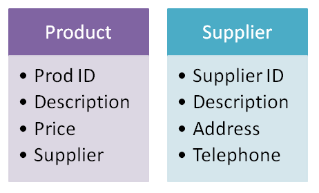
There are a number of ways to represent an entity. You just need to choose one and stick to it. The one below shows a simple box with the name of the entity at the top. Its attributes appear as a list within the box.
The diagrams below show an entity called 'Product' and and entity called 'Supplier'

Notice the attribute Prod ID. This is a unique reference to each instance of 'Product'. It is called the 'primary key'. Likewise, the supplier entity has a primary key called Supplier ID. Of course you do not have to use 'ID', it happens to make it easier to spot the primary key.
Another way of representing an entity in text format is shown below
PRODUCT (Prod ID, Description, Price, Supplier)
The name of the entity is in capitals, and its attributes are contained within a set of brackets. The primary key is the first in the list.
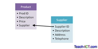
Notice the attribute called supplier in the Product entity. The first thought might be to store the name of the supplier in there, such as 'Kellogs'. This is not a good idea - what if Kellogs change their name for some reason? Every single product record supplied by Kellogs would have to be changed.
A better way is to store the primary key of Kellogs from the Supplier entity. Now if the contact details are changed, this will have no effect on the Product entity. This is called a 'foreign key'. A foreign key is always the primary key of another entity. You can have a number of foreign keys within an entity.

The next thing to know about ER diagrams are the possible relationships between them.
challenge see if you can find out one extra fact on this topic that we haven't already told you
Click on this link: Drawing ER diagrams
